
Connection of the wiring analyzer to the product being tested is critical to a successful test setup. The DIT-MCO test programming language allows test scripts to be written and executed using the connector and pin names of the product being tested instead of simply using the analyzer’s front panel pin numbers.
Adapter cables connect the UUT to the wiring analyzer. The wiring analyzer should be made aware of which product test points are connected to the analyzer’s test points, and this is done using an Address Correspondence Table, or ACT file. Each entry in an ACT file describes a connection to an analyzer pin. For example, if the product to be tested has a three-pin connector named J1, with pins A, B, and C, the ACT file entries would be as follows:
| Analyzer Address | Connector | Pin Label |
|---|---|---|
| 00000 | J1 | A |
| 00001 | J1 | B |
| 00002 | J1 | C |
Without the use of an ACT file, a test for continuity between J1-A and J1-C would be written using analyzer test point addresses:
X00000
C00002
However, when an ACT file is used along with a test script, the same test is much more identifiable when compared with the schematic:
X-J1-A
C-J1-C
Using ACT files benefits programmers and users by allowing them to easily locate an address on a schematic.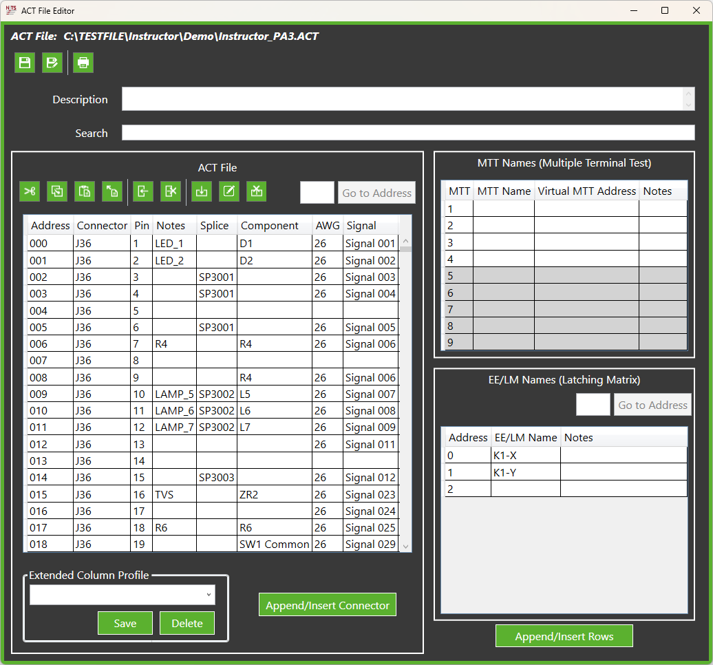
Test programmers create ACT files as part of the Test Script creation process. The window above is the ACT file generator. It shows the Connector-Pin information for each analyzer address.
Additional information has been included in this ACT file to further assist users when troubleshooting errors. For example, wire splice information is available. Notice that J36-3 and J36- 4 are part of Splice 3001.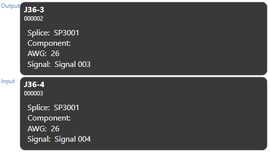
That splice information is then displayed in the Test Execution screen when diagnosing a continuity error. This information is available only because it was included in the ACT file in an additional column.
Source: NETS User Manual, Revision D, document 132-06035-0006, section 4.5.