
Use a continuity test to:
- Verify wire-to-wire connections
- Detect open circuits
- Confirm component connections
- Validate wiring before insulation or Hipot testing
Two-Wire Continuity Test
A standard two-wire continuity test measures resistance between two points using one output address and one input address. This is the most commonly used continuity test in NETS.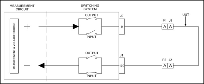
Example Test Setup
Example:
- Connector J1 Pin A is connected to Output Address 0
- Connector J2 Pin A is connected to Input Address 100
The required test instructions are:
X0
C100
Where:
- X0 connects Address 0 to the output.
- C100 connects Address 100 to the input.
The analyzer then performs the programmed continuity measurement.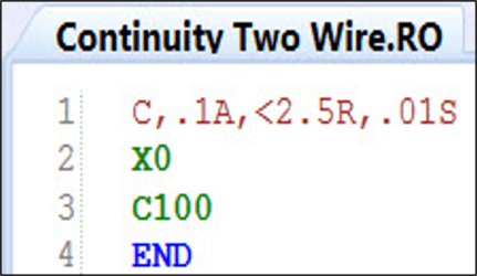
Reverse Test Script
NETS executes the reverse continuity test using the same parameter statement with the addresses reversed.
This is useful when diagnosing switching path issues.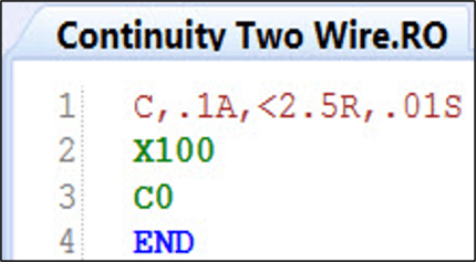
Four-Wire (Kelvin) Continuity Testing
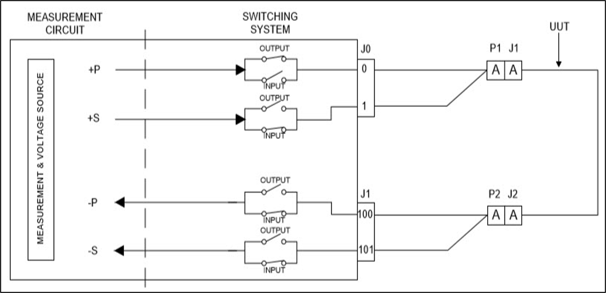
For applications requiring greater measurement accuracy, NETS supports Four-Wire (Kelvin) continuity testing.
When Kelvin mode is enabled:
- Odd addresses become Sense
- Even addresses become Power
This method minimizes measurement error caused by lead resistance.
Enabling Kelvin Mode
Before running a Four-Wire test, execute:
ENB, KEL
Then perform the continuity test using the same X and C commands as a standard two-wire test.
Example:
ENB,KEL
X0
C100
Kelvin mode can be enabled only when needed and turned off afterward. Adapter cables must also support Kelvin testing. 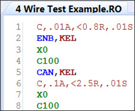
Best Practices
- Use Two-Wire continuity testing for most wire harness applications.
- Use Four-Wire (Kelvin) testing when higher resistance accuracy is required.
- Verify the correct addresses before running the test.
- Reverse the test direction when troubleshooting possible switching path issues.
- Ensure adapter cables are compatible before enabling Kelvin mode.
Troubleshooting Tips
Test Fails in One Direction Only
Possible causes:
- Switching relay issue
- Input relay fault
- Output relay fault
Try performing the reverse continuity test to help isolate the problem.
Unexpected Resistance Reading
Possible causes:
- Incorrect test limits
- Poor adapter connection
- Damaged wiring
- Lead resistance (consider using Kelvin mode)