
Since distributed switching systems do not have a terminal selector unit, they use flash memory on the switching cards to define what location they are in the switching system. This information must be downloaded into the hardware when initially set up or when modules or switching cards are added or changed. The DSC feature allows users to create and edit a text file that defines the physical location of switching point addresses in Series 10 and 19-based distributed switching analyzer systems. This feature also helps to identify external energization (EE)/latching matrix (LM) points in the system. Addresses may be defined individually or in blocks using “SPAN” definitions.
Switching addresses are defined in this format: D0000=M000 S0 C0, where:
D = DIT-MCO Connector Address
M = Module Address (0-255)
S = Slot Address (0-14)
C = Connector (0-2)
If the system contains any External Energization (EE) or Latching Matrix (LM) points, they must also be defined. LM addresses are defined in this format: LM0000=M000 for standard built-in 10 points of LM in a switching module, or L200=M000 G0 for LM modules, where:
L = Latching Matrix relay
M = Module Address (0-255)
G = Group (Within a Module) (0-1)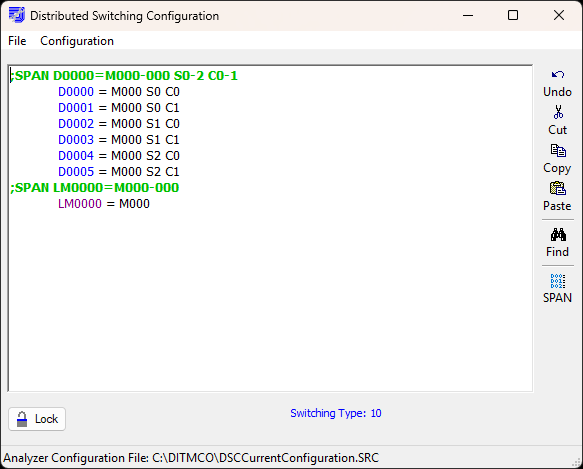
8.2.3.1.1 Configuring a DSC File
Open the Distributed Switching Configuration window and click SPAN. Enter the information for DIT-MCO Connector Address SPAN data fields only: do not configure the latching matrix at this point, or the switching information entered will not be saved.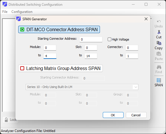
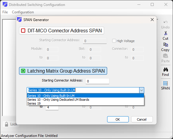
The DSC file now contains the switching configuration information entered in the SPAN Generator. Click the SPAN button again to configure the latching matrix addresses. There are three options for LM:
- Series 10 - Only Using Built-In LM. Select this option if the switching modules contain only the default 10 LM points built into each module.
- Series 10 - Only Using Dedicated LM Boards. Select this option if the system has LM modules attached.
- Series 19. Select this option only for 2135 and 2600 systems.
The DSC file is now fully populated and shows both switching and LM configuration data. The switching data starts at the top of the file: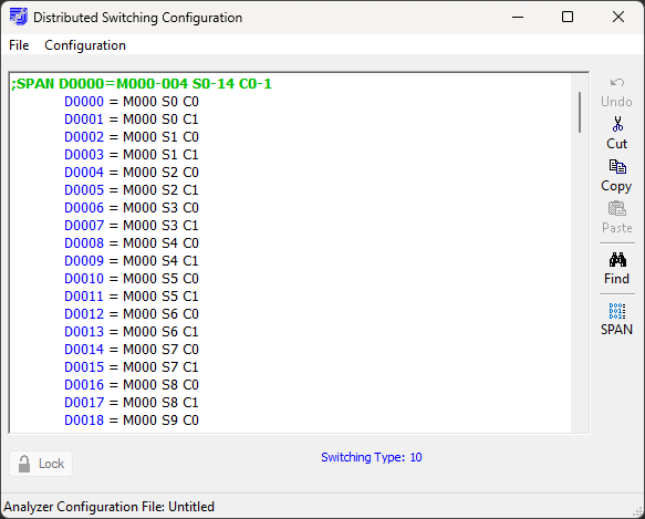
The latching matrix data is recorded after the switching data ends: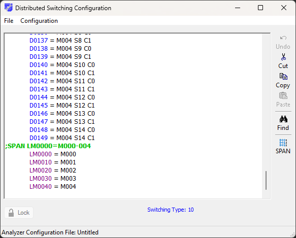
The configuration information must then be sent to the system so NETS can access all switching and LM points. Click Configuration > Compile and Download to send the DSC file to the system.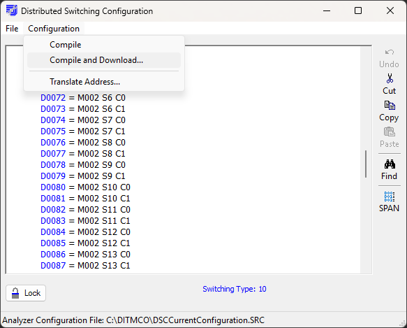
Once the download is complete, the Series 10 switching and LM configuration is properly recorded. Click on File > Open Current to view the current DSC data to validate that the correct information was recorded.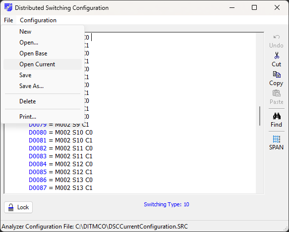
A helpful feature is found under Configuration > Translate Address. It allows users to enter a machine address within range of the switching configuration and translate it to its physical location. Illustrated below is address 2949 located in Module 0, Slot 14, Connector 1.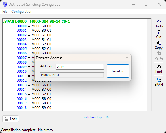
Source: NETS User Manual, Revision D, document 132-06035-0006, section 8.2.3.1.