
Tare is the amount of resistance that should be subtracted from the measured value to obtain a more accurate resistance measurement to determine a pass or fail condition. Tare can occur internally within the analyzer to its front-face connectors, from end to end in adapter cables, and in capacitors in the UUT.
8.2.1.1.1 Analyzer
NETS uses a Tare Map to determine the more accurate methods for improving two-wire testing. This map is created on all analyzers during testing at DIT-MCO before being shipped to customers. In many cases, updating tare maps on a schedule is unnecessary, especially if the analyzers are kept in favorable operating conditions, e.g., 60 to 90 degrees Fahrenheit (15.5 to 32.2 degrees Celsius), 20- 80% non-condensing humidity, and no salt in the air. If analyzers are used in unfavorable or environmentally harsh conditions, tare maps may need to be updated on a consistent basis to ensure the most accurate resistance values are used during testing. See Tare Mapping the Analyzer in this section for instructions for updating tare maps.
8.2.1.1.2 Adapter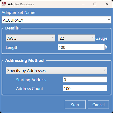
Selecting the Resistance button in the Adapter section will open an Adapter Resistance panel. The Adapter Resistance panel is divided into two (2) sections: Details and Addressing Method. In the Addressing Method section, the user specifies how the NETS software addresses the Adapter connectors.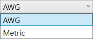
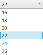
The Details section is where users provide more informatoin by selecting AWG or Metric to designate the wire size of the adapter. The user also selects the cable length and can give an Adapter Set name for easy retrieval in the future.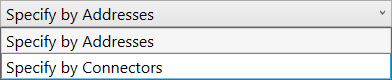
Users have two (2) options for the Addressing Method:
- Specify by Addresses - Enter the adapter device's Starting Address and Address Count to define a range of addresses to test.
- Specify by Connectors - Select the number of the first and last connectors by selecting the connector number from the dropdown list.
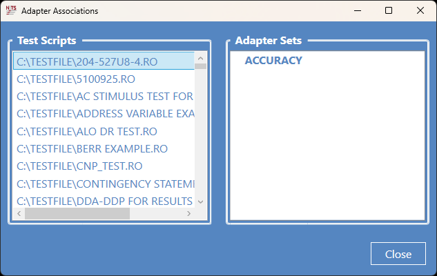
The Associations feature allows users to associate a test script with an adapter set. This feature causes an adapter to be automatically characterized by its association with a Test Script that is being run. The left side of the Adapter Associations panel shows the available Test Scripts in the system’s database. The right side of the Adapter Associations panel shows the available Adapter sets that may be associated with a Test Script. Once a Test Script has been associated with an Adapter set, tare values stored in the adapter set database will be used for the associated Test Script when enabled using ApplyResistanceTare or ApplyCapacitanceTare modes.
8.2.1.1.3 Product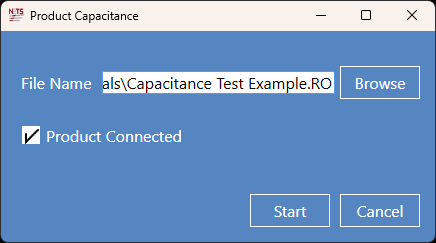
Clicking the Capacitance button opens the Product Capacitance panel, as seen in the figure. Users may search for the capacitance test script associated with the product to be tested. After the device to be tested has been connected, check the Product Connected box. Clicking the Start button will take the user to the Test Screen, where the script will be executed.
8.2.1.1.4 View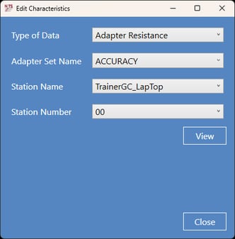
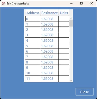
Click the View button to see the stored resistance and capacitance values. The figures above show the Adapter Resistance for the ACCURACY Adapter Set defined earlier in this section.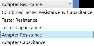
Users have five (5) viewing options to choose from:
- Combined Tester Resistance & Capacitance
- Tester Resistance
- Tester Capacitance
- Adapter Resistance
- Adapter Capacitance
Tester and product capacitance refers to the ability of those systems to hold an electrical charge using the capacitors in each product. Cable capacitance is the measurement of the electrical charges stored within it. The capacitor in the cable is constructed by two conductive materials separated by an insulator or dielectric. The cable's capacitance determines the charging current, charging KVA, and dielectric loss. KVA, or kilovolt-ampere, is a unit of measurement for apparent power in an electrical system, representing the total power used.
Source: NETS User Manual, Revision D, document 132-06035-0006, section 8.2.1.1.