
2650 Modular Test Analyzer

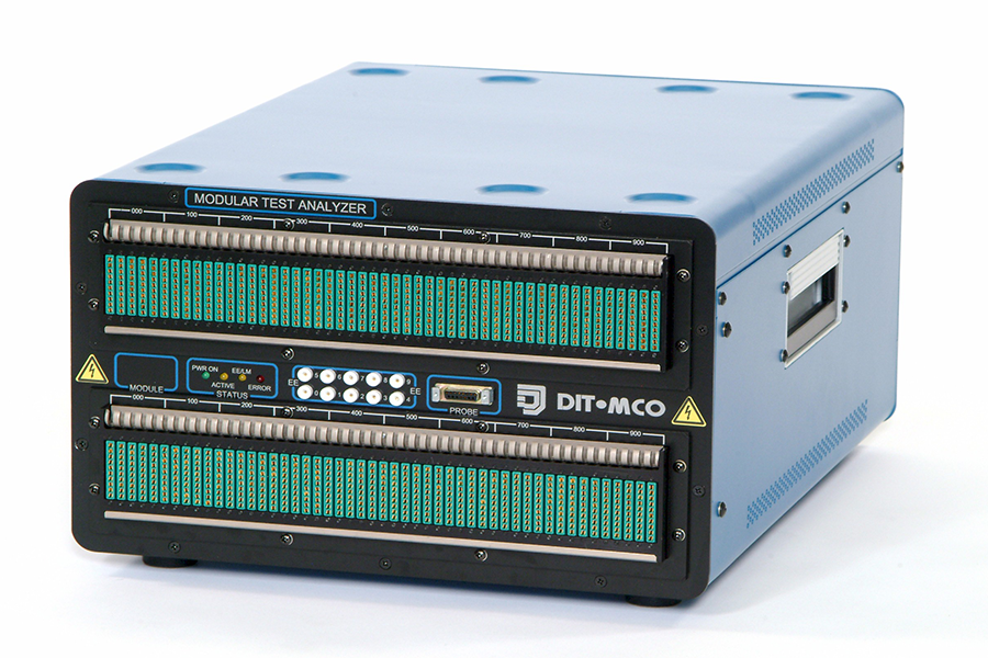
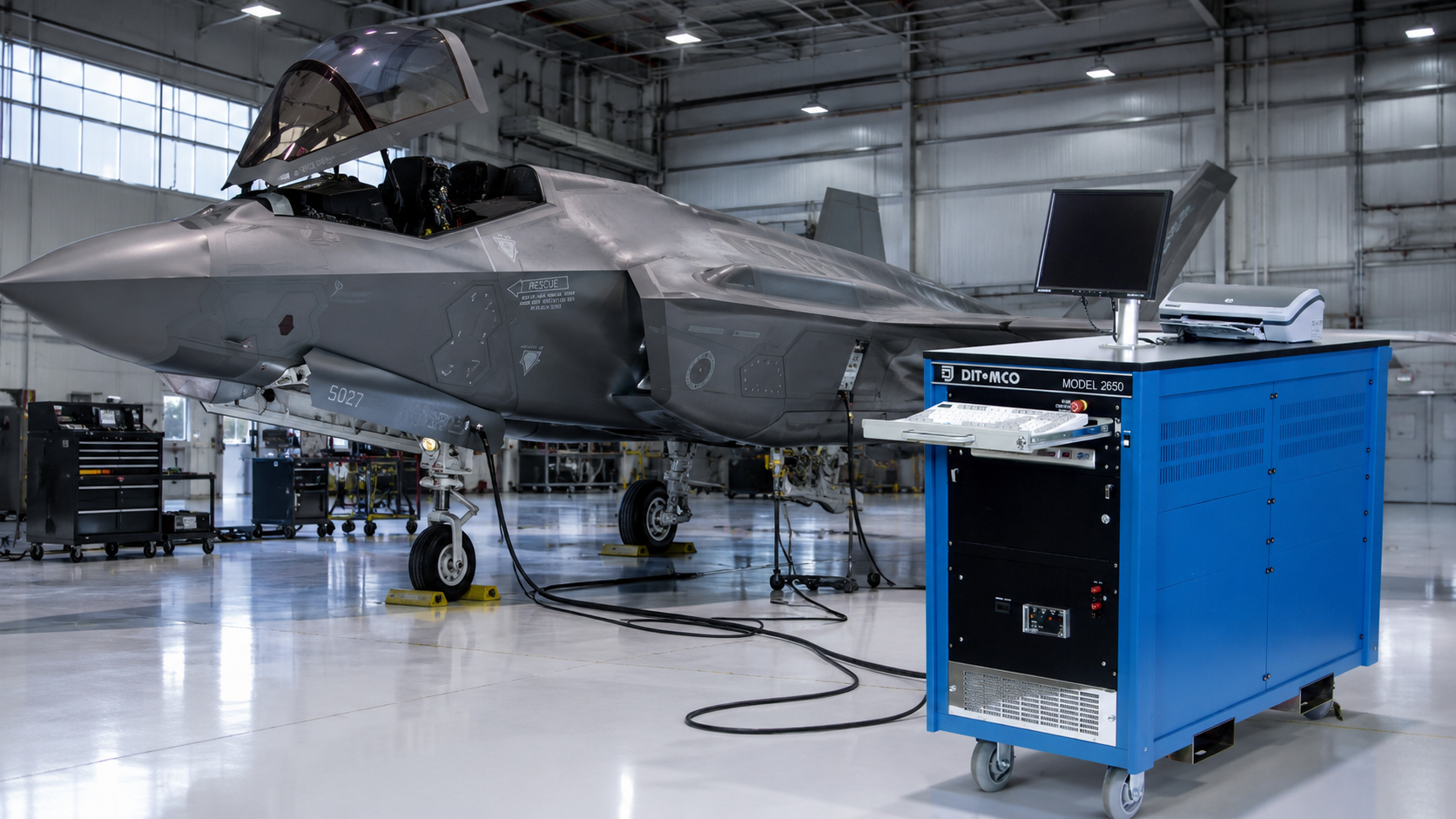
The Model 2650 delivers a modular, scalable wire harness testing platform that can be centrally configured or distributed around the unit under test, reducing adapter cabling while adapting and expanding as your requirements evolve.
Flexible Testing Built Around Your Application
The Model 2650 wiring harness analyzer provides a modular, scalable testing platform that can be configured around your product and production environment. Switching units can be rack-mounted together for concentrated test-point capacity or distributed around the Unit Under Test (UUT) to reduce long, cumbersome adapter cables. As your requirements or product configurations change, the system can be reconfigured and expanded without replacing the entire test platform.
Simplify Testing for Large Complex Assemblies
Large aircraft, vehicles, and other complex UUTs can make centralized testing inefficient and create costly cable-management challenges. The Model 2650 brings switching capacity closer to the product, reducing adapter cable length, simplifying storage, and minimizing the time and expense associated with cable rework.
Configure the Right Capacity Without Overinvesting
The Model 2650.MTA is DIT-MCO’s most flexible test system, supporting multiple test stations from a single controller to help reduce the total cost of testing. Interlocking switching modules can be securely stacked for mobility, rapid deployment, and efficient use of production space.
Each standard switching module supports up to 1,500 test points and can be configured in 100-point increments, allowing you to purchase only the test capacity you need. Standard interfaces include 150-point ZIF and 50-pin D-sub connectors, with customized interface options available for specific applications.
Compact 500-point switching modules are also available for areas where space, weight, or test-point requirements are limited.
Access Power and Test Points Where You Need Them
External energization and test-probe connections are built into each switching module, providing convenient access to points that require power, measurement, or troubleshooting.
Applications requiring additional external energization capacity can use dedicated switching modules configured with EE cards. These modules can be positioned and integrated into the system in the same way as standard switching modules.
Reduce Setup Time and Eliminate Hookup Errors
The Model 2650’s optional random hookup capability simplifies adapter cable connection and accelerates test preparation. Operators can connect adapter cables in any order while embedded identification automatically determines each cable and its location. The system then matches the physical hookup to the test program and runs the test as written—without requiring program changes, manual cable sequencing, or additional setup steps.
Model 2650 HVA & MBA Options
Model 2650.HVA
The Model 2650.HVA provides high voltage stimulus up to 2000 VDC and 1500 VAC.
The Model 2650 HVA controller supports both high-voltage and low-voltage switching modules. You can use both in a single test setup, and the controller will disable the low-voltage switching if a high-voltage test is programmed.
Depending on the interface connector, the switching module holds up to 750 test points.
Model 2650.MBA
Integrate the 2650.MBA (Multiple Bus Architecture) into your current test and manufacturing process. The 2650.MBA tests subassemblies containing relays, switches, solenoids, lights, LEDs, and programmed power sources. Whether you need external stimulus to actuate components or add instruments, the 2650.MBA offers an efficient test solution. It eliminates unique adaptation with its direct connector-to-connector design, cutting costs and time. You can test panels, chassis, electrical racks, and other wired assemblies containing active components.
The Difference in Energization
The MBA is unique because it allows any point in the analyzer to be a switching point or an energization point. Its random access, multi-bus architecture eliminates unique interfaces.
- Portable
- Reconfigurable
- Distributed
- Minimizes Adapters
- Maximizes Space
- Multibus Option
- Random Hookup Option
Additional Information and Specifications
The DIT-MCO Model 2650 Modular Wiring Analyzer is designed for flexible, scalable automated testing of cables, wire harnesses, panels, and other complex wired assemblies. Its modular architecture allows switching units to be centrally rack-mounted, stacked for mobility, or distributed around the Unit Under Test (UUT) to reduce adapter cable length, handling, and storage requirements.
The Model 2650 supports multiple test stations from a single controller and provides highly flexible switching configurations through virtual test addressing. Each standard switching module supports up to 1,500 test points, while system segments can support up to 15,000 test points. Specialized 500-point modules are also available where reduced size and weight are beneficial.
Flexible & Distributed Architecture
The Model 2650 is built around modular switching units that can be positioned wherever they are most useful. Modules can be rack-mounted, stacked on a trolley, distributed around a large assembly, or combined in mixed configurations. A single daisy-chain connection links the switching modules, simplifying installation and helping reduce long adapter cables.
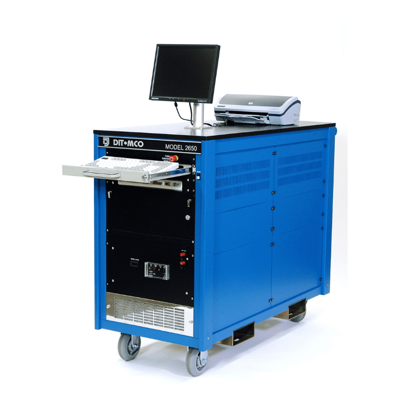
The control module is available in both bench and cabinet configurations. A bench controller can drive up to 15,000 test points in a single segment, and additional drivers can be added for larger systems. Cabinet configurations are available for applications requiring additional instrumentation, power supplies, or larger switching systems.
Faster Hookups & Random Hookup Capability
An optional Random Hookup feature allows operators to connect adapter cables to any convenient test-system connector without following a fixed hookup sequence. Electronic identification embedded in the adapter cables allows the system to recognize each adapter, associate it with the correct test address, and execute the approved test program without modification.
This capability helps reduce setup time while maintaining consistent test addresses, test sequences, and error reporting regardless of where the adapters are connected.
Functional Testing & Multiple Bus Architecture
The optional Multiple Bus Architecture (MBA) extends the Model 2650 beyond standard wiring analysis into functional testing of relay chassis, control panels, and other assemblies containing active components. MBA switching can route power supplies or instrumentation to selected circuits through the tester without requiring split or “Y” interface cables.
Each MBA switching board provides 50 test points and 50 two-bus energization points. Depending on configuration, the system can support multiple power buses for distributing power or instrumentation throughout the test system.
High Voltage Testing
For applications requiring higher dielectric test levels, optional High Voltage Architecture (HVA) switching provides access to the UUT with stimulus up to 2000 VDC / 1500 VAC. HVA modules use a separate switching bus to isolate high-voltage circuits from standard switching. Standard, MBA, and HVA switching modules can also be combined within the same overall system.
External Energization & Latching Matrix Options
The Model 2650 provides built-in support for external energization of components during testing. Four power-supply buses can be distributed through the standard module interconnect, allowing relay and component activation without additional external routing cables. Each switching module includes external energization relay capability for program-controlled power application.
Optional Latching Matrix (LM) boards provide additional program-controlled relay points for higher-power or specialized functional testing applications. LM configurations can be integrated into standard switching modules or provided in dedicated modules for applications requiring large numbers of energization points.
Easy Maintenance
Rear access to the switching electronics allows switching cards to be serviced without disconnecting the adapter cables from the front of the system. This design helps reduce maintenance time and overall system downtime.
Test & Switching Capacity
- Switching Capacity per Standard Module: Up to 1,500 test points
- Switching Increments: 50 points
- Expandable Capacity: Up to 15,000 test points per segment
- Test Speed: Up to 3,000 tests per minute
- Switching: Heavy-duty electromechanical dual “Form C” relays
- Discharge Wait Circuit: Prevents switching from actuating while stimulus is applied
Standard Instrumentation
- Voltage Stimulus: Up to 1500 VDC
- Current Stimulus: Up to 2 A
- Continuity Resistance: 0.01 Ω to 99 kΩ
- Insulation Measurement: Up to 1000 MΩ
- Four-Wire Resistance: 0.01 Ω to 10 Ω
- Capacitance Measurement: 10 pF to 5000 µF
- Continuity Accuracy: ±1%
- Insulation Accuracy: ±3%
- Instrument Configuration: Floating
- Simultaneous insulation and hipot testing
- DC Dielectric (Hipot) Current: 0.5 mA to 2.5 mA
- DC voltage measurement
- AC voltage measurement, true RMS
Additional Instrumentation
- Optional AC Dielectric Detector: 1000 VAC
- Optional HVA Testing: Up to 2000 VDC / 1500 VAC
Switching Unit Dimensions
Standard Module
- Width: 17.38 in (441.45 mm)
- Height: 11.3 in (287.02 mm)
- Depth: 22.25 in (565.15 mm)
Mini Module
- Width: 8.63 in (219.20 mm)
- Height: 11.3 in (287.02 mm)
- Depth: 22.25 in (565.15 mm)
Optional Switching Architectures
- MBA: Multiple Bus Architecture for component and functional testing
- MBA Bus Capacity: Up to four buses
- HVA: High Voltage Architecture for tests up to 2000 VDC / 1500 VAC
- Standard, MBA, and HVA modules may be combined within a single system
MBA Matrix Ratings
- Maximum Switching Power: 62.5 VA / 60 W
- Maximum Switching Voltage: 250 VAC / 220 VDC
- Maximum Switching Current: 2 A
External Energization Ratings
- Maximum Switching Power: 1250 VA / 150 W
- Maximum Switching Voltage: 250 VAC / 30 VDC
- Maximum Switching Current: 5 A
Latching Matrix Ratings
- 20-Point LM Board
- Maximum Switching Power: 1250 VA / 150 W
- Maximum Switching Voltage: 250 VAC / 30 VDC
- Maximum Switching Current: 5 A
- Dedicated LM modules are available for applications requiring additional energization points
Operating Conditions
- Operating Temperature: 60°F to 90°F (15°C to 32°C)
- Relative Humidity: 30% to 80% RH, non-condensing
- Application Environment: Indoor
Power Requirements
- 115 VAC / 20 A, single-phase, 60 Hz ±10%
- 208 VAC / 30 A, three-phase, 60 Hz ±10%
- 100–110 VAC / 25 A, single-phase, 50 Hz
- 220–250 VAC / 15 A, single-phase, 50 Hz
Standard Software
TestLink® software includes:
- TestEdit®
- TestExecutive® with self-programming
- Write Error Program (WEP)
- Compensated Continuity Resistance (CCR)
- Syntax Checker (SYNCHK)
- Diagnostics
Software Options
- TestAssistant® II
- Communications and networking
- APG/WIRESORT
- TestStats® Statistical Database
- Checksum (CHKSUM)
- Language Translators
Hardware Options
- Continuity probe
- Wireless remote control terminal
- Bar code reader
- External power for relay/component energization or instrumentation support
- Customer-specified connector interfaces
- Latching Matrix for external energization

Wire Harness Tester Service and Training Guide
How to Fix Inconsistent Hipot Test Results in 7 Steps (2026)